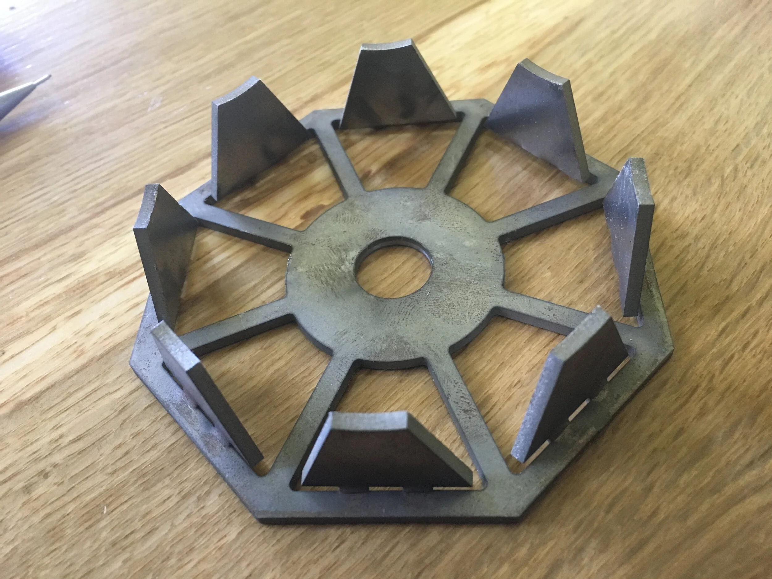
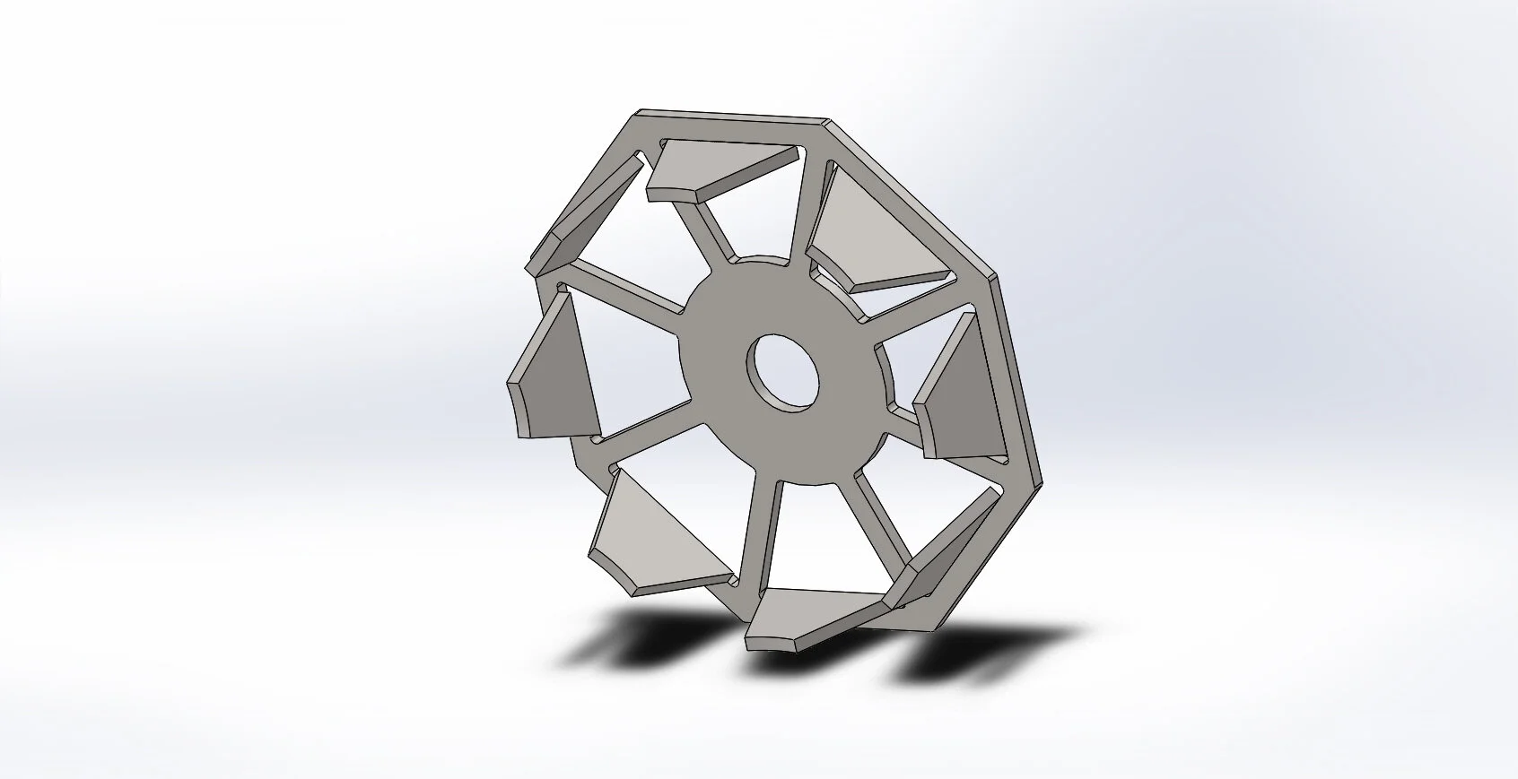
Lotus Flywheel
Goal:
Redesign a flywheel for a sterling engine using 1/8” steel plate cut on a waterjet (no other processes allowed). The overall diameter can’t exceed the original, the center hole must be 14mm and the moment of inertia must be the same as the original. Minimize manufacturing costs.
Process:
An octagonal outer shape was selected so that more units could be cut out of a single sheet of steel. The material loss between units would be near zero compared to using a shape like a circle.
By bending the “leafs” outward, it moved mass away from the center which increases the moment of inertia (MoI). Initially this resulted in a MoI larger than the original flywheel, so the overall size of the flywheel was reduced until the desired MoI was achieved as well as increasing the number of units produced per sheet. Solidworks was used to make this analysis.
In the end, the only wasted material was the loss from the kerf of the waterjet cut and the 14mm hole in the middle. A square design was considered to further minimize material loss at the edges of a sheet of material, but this inefficiency was deemed acceptable for the gain in aesthetics.

